Overview
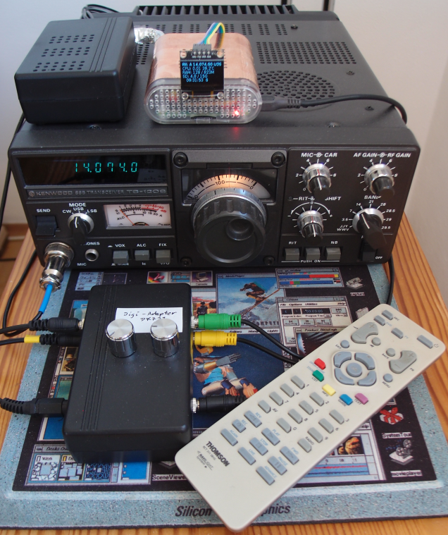
I own a Kenwood TS120S ham radio transceiver (with original PS30 power supply)
built in 1979.
It was one of the first inexpensive transceivers with PLL and digital frequency display.
It weighs a few pounds but was called a mobile transceiver at the time.
The service manual and a lot of informations about the transceiver
were collected by radio amateurs and are available on the internet.
Thanks to this information a faulty transistor could be located and replaced.
Because of the free running VFO, in the first hour of operation
the frequency needs to be adjusted every few minutes.
Therefore I decided to build a DDS VFO. A DDS VFO also improves FT8 operation
because of split frequency support and remote frequency control.
Hardware
The components:
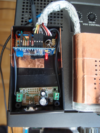
- AD9850 DDS module
- 5V voltage regulator module
- remote control from an old DVB receiver
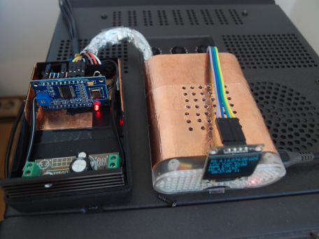
- small box for the VFO parts
- RPi with RASPIOS and Python3 and LIRC software (I use a RPi3)
- small OLED screen (ssd1306) for status display
- IR receiver
From the TS120S service manual an external VFO has to deliver a signal of 200mV rms at 500 Ohm in frequency range 5.5 Mhz - 6.0 Mhz This is exactly the voltage the chinese AD9850 DDS module produces. Therefore it should be no problem to adapt the module to the external VFO input of the TS120S transceiver.
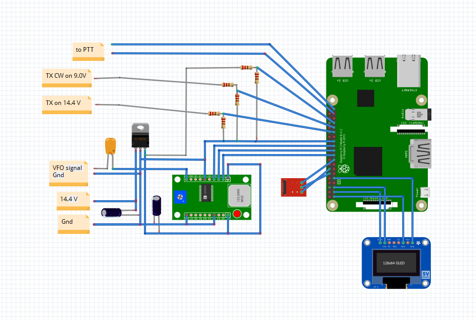
The external VFO connector of the transceiver provides tho following lines:
- Gnd
- 9V, regulated, not specified but from docs limited to ~25-30 mA
- 14.4V, unregulated, directly from PS
- TX on (14.4V)
- TX-CW on (9V)
- shielded VFO signal input
The AD9850 DDS module needs 5V, ~130 mA. To power the module from the transceiver the 14.4V line must be used. To get the 5V a standard voltage regulator module is used (LM7805 + 2 capacitors). This results in a heat problem because the voltage regulator produces (14.4-5)V * 0,13A ~= 1.2W as heat. The standard cooling shield of the module was replaced by a larger shield of a DRAM module. Additionally 54 holes were drilled in the small box for better cooling.
Copper tape connected to ground is used on the inner side of the small box to shield the VFO.
The RPi runs a standard RASPIOS with Python3 and LIRC for IR handling.
Simple voltage dividers are used to adapt the three lines TX on, TX-CW on, 5V to three GPIO-in input lines (max. 3.3V) of the RPi:
- RPi Pin29 GPIO5, 56k/15k 14.4V => 3.0V
- RPi Pin31 GPIO6, 47k/22k 9.0V=> 2.9V
- RPi Pin33 GPIO13, 33k/47k 5.0V => 2.9V
- RPi Pin30 Gnd
A TSOP IR receiver is connected to a GPIO-in pin, 3.3V and ground of the RPi:
- RPI Pin12 GPIO18 signal
- RPi Pin14 Gnd
- RPI Pin17 3.3V
The small OLED display uses SPI protocol and is connected to two GPIO-out pins, 3.3V and ground:
- RPi Pin1 3.3V
- RPi Pin3 GPIO2 data
- RPi Pin5 GPIO3 clock
- RPi Pin9 Gnd
To program the DDS module three GPIO-out lines of the RPi are directly connected to the input lines of the AD9850 module:
- RPi Pin21 GPIO9 sync
- RPi Pin19 GPIO10 clock
- RPi Pin23 GPIO11 data
- RPi Pin25 Gnd
One GPIO-out line is connected to the PTT input line of my data box:
- RPi Pin37 GPIO26
- RPI Pin39 Gnd
Please note that the normal RTS signal is 5V or higher and negative (inverted), but the GPIO-out signal is 3.3V only and is positive. My home built data box can handle both signals using an opto coupler and an internal inverter.
The system worked fine on 20m, but on 10m band the system showed strange effects until the cover of the RPi was shielded. I used grounded copper tape as for the box.
Software
The DDS VFO itself has no controls.
The RPi accepts IR input, mouse input and commands from a HAMLIB client for the VFO.
(e.g. in WSJT FT8 software select HAMLIB as transceiver model and specify the HAMLIB port
4575 as declared in the python script)
The software consists of two Python scripts.
- dds.py for VFO control, IR input, mouse input and HAMLIB input.
The software emulates two VFO's.
-
Supported keys by IR remote control and mouse:
- left/right keys adjust the step size 10-100-1000-10000
- up/down keys change frequency based on step size
- 3 digit input for numeric frequency input 0-500 kHz
- OK key toggles VFO
- Colored key of remote are used for 5 memories to store/recall frequencies
- record key toggles ptt, switches tx on/off
- pause key toggles split mode
- forward/rewind keys select the band
- next/last keys select the mode
- mouse wheel changes frequency based on step size
- left/right mouse buttons adjust the step size 10-100-1000-10000
- wheel mouse button toggles VFO
- stats.py for the RPi status display
- irexec.lircrc The TUNER/AV key is used to start the VFO.
- lirc_options.conf
- lircd-thomson-rct311.conf
Update for Version 2
Hardware
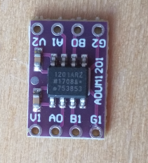
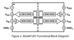
In a second version of the DDS-VFO I added three ADuM1201 boards to isolate the VFO from the RPi.
Like optocouplers the ADuM chips isolate input and output. The ADuM1201 is symmetrically and offers one input and one output per side.
The ic can also do 3.3V to 5V conversion.
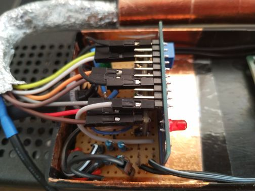
Three boards in a row just fit below the pins of the AD9850 module.
The RPi side is powered from the RPi with 3.3V, the AD9850 side with 5V. This requires an
additional 3.3V line from the RPi. For this reason the OLED screen was moved to 5v power connector from the RPi.
The AD9850 module has been mounted in the reverse position compared to the first version, the SPI pins are now
at the bottom and connected to the ADuM1201 outputs on the bottom row.
The top row of the three ADuM1201 boards forms the 3.3V side and is connected to the RPi.
In the first version, the third voltage divider to the GPIO-13 input line was used to signal the power-on state of the TS120S.
GPIO 13 is now connected directly to an output of the ADuM1201, eliminating the need for the voltage divider.
Because the output of an ADuM1201 is HIGH when the input is unpowered, the logic for power-on detection had to be inverted.
LOW now signals the RPi that the TS120S is powered.
Software
The software dds-v3.py was extended by a bluetooth server to handle serial-over-bluetooth commands from clients.
The reason: The FT8CN app for FT8 on Android has no built-in hamlib client and the app worked fine controlling
my Yaesu FT818 using serial-over-bluetooth. To control the TS120S from FT8CN without an USB cable I needed a bluetooth or ICOM style network connection. Because I don't have any experience with ICOM protocols I added a bluetooth serial server to accept Yaesu FT818 style commands
for VFO selection, frequency settings and PTT control.
In version 3 handling of multiple connections was fixed. An integrated bluetooth agent for pairing was added.
Because sspmode=0 with fixed PIN worked only to Win7 bluetooth but failed to Android 9 and 15 sspmode=1
with 'DisplayYesNo' is implemented.
- Button KEY_RADIO on remote (or keyboard) sets the VFO discoverable
- On a paring request from client a code is send to display and must be confirmed by KEY_OK on remote (or keyboard).